PC Q&A
19/03/13(Tue)22:01


Ask the experts..and then here!

  • Supported file types are: GIF, JPG, PNG
  • Maximum file size allowed is 8000 KB.
  • Images greater than 200x200 pixels will be thumbnailed.
Subject (Optional)
Comment
File (Optional)
Submit

30/11/14(Sun)22:39

yeah, MalwareBytes is on all my 'puters. The rest all run mse. only this one (W8.1) has defender. I wish Malwarebytes did real time protection.

30/11/14(Sun)19:41

>>29570 The best thing to do with defender is switch it off :D
I currently use Avast, but have used Comodo too but it caused my laptop some issues. I always keep MalwareBytes AntiMalware on my computers too just in case something did get through.

30/11/14(Sun)11:37

Ah yes, technically called an 'unmanaged switch' but we usually call them 'dumb switches'.
I like 'clueless switch' better though and will start using that now :D

29/11/14(Sat)20:59

my IT-techer used this term (in Dutch) and I used Bing to translate :( (what was I thinking??)
Things are working grand now.

Although, I do have this thing with Defender not installing any updates, however it downloads them just fine. I have to do this manually. What virus scanner do you use..if any?

29/11/14(Sat)12:39

I've never heard the term 'clueless' used for any kind of network equipment, just for the people trying to use them, like me! XD

28/11/14(Fri)22:08

oh..my fingers typed before brain thought. I meant clueless switch (aka a hub).

And no need to fucking swear, ffs. ;)

28/11/14(Fri)19:58

>>29558 What the fuck is a clueless hub?

28/11/14(Fri)16:21
100.3
(100.3 Kb, 1462x635)

this feels so good. My old switch was just 10/100Mbit/s, so yeah :D

28/11/14(Fri)11:15

thx, I just bought a switch with more ports. Better safe than sorry. Would a clueless hub made a difference?

28/11/14(Fri)10:57

>>29538 You can daisy-chain switches but it can make the network run slow, best to route it back to the router/modem if you can.

26/11/14(Wed)12:44

Can I add another switch to my network? I already have one but it has 1 port left, also the cables clutter is getting out of hand.
So I hope to add the second switch to the first. Or would it be better to route it straight from the router/modem?

golly, what an old thread!

30/03/13(Sat)12:41

>>23261 Very nice :)

30/03/13(Sat)02:17
1823.3
(1823.3 Kb, 3264x2448)

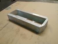
update on the pedestal

>>23097 no luck :( Will use a spare mobo header

24/03/13(Sun)18:26

>>23090 You may be able to use google to find a pinout for that header

23/03/13(Sat)21:58
2619.0
(2619.0 Kb, 2832x2128)

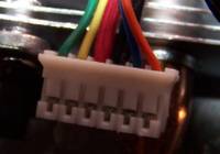
6 pin fan connector (circle)

23/03/13(Sat)21:53
204.5
(204.5 Kb, 857x600)
graphics card fan connector (2x3)

Yeah, SpeedFan works. I can control/adjust the graphics card fans. I still have a few empty 4-pin headers left on the mobo. I could play around with that, thx man!

23/03/13(Sat)14:05

I wonder if you could read the temp from the GPU sensor in software, such as speedfan, and then use that temperature to control the fan speed of one of the mobo headers instead of the GPU fan speed?
Not sure why the fan header on the GPU would be any different than a mobo one either. Surely it's a 3 wire fan on the gpu?

23/03/13(Sat)11:54
64.7
(64.7 Kb, 685x684)

That arduino looks similar to this http://koolance.com/tms-205-software-thermal-interface-controller

23/03/13(Sat)11:45
1554.6
(1554.6 Kb, 2128x2832)
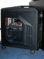
CM Storm Trooper

>>23074 arduino? :S
Actually I wanted to use the GRAPHICS CARD fan controller. But that has never been done..and I don't have all the right tools.

So I'll use a motherboard fan header instead. The mobo doesn't read the graphics card temp unfortunately :(

I have already set up a water cooling system to cool the processor and yes that one uses a mobo fan controller (header).

>>23072 He and I know each other from a tech forum. And he has delivered custom build parts already, so I'm not too worried.
I do know it's in the USA ;)

The pedestal he's building for me is custom made, specific for the case I have (CM Storm Trooper/Stryker)

23/03/13(Sat)10:37

You need to learn how to use this arduino.cc/ . Then you can make an LCD controller and Temp sensor system.
Seems to me you want to be using one of the fan controllers on the motherboard to control the pump. It would read the temp sensor and ramp up the speed of the pump accordingly. I'm sure other people must have done this.
Separate loop for GPU sounds like a good idea to me.

22/03/13(Fri)22:36

Is that a stock item (pedestal) or custom made for your particular pc. I couldn't find where the company was located.

22/03/13(Fri)17:16

He's got a website http://triptcc.com/

22/03/13(Fri)16:02

That should hold up a school building. Nice shop from what I can see.

22/03/13(Fri)10:06
2663.9
(2663.9 Kb, 1217x900)

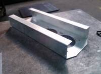
here's the actual pedestal (wip)

21/03/13(Thu)18:55

Wonderful! Let me see how you get it all installed and how you switched it when you're done. Maybe there won't be any soldering.

21/03/13(Thu)11:42
49.5
(49.5 Kb, 1618x851)

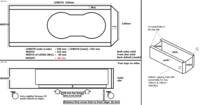
specs

21/03/13(Thu)11:39
14.3
(14.3 Kb, 633x555)

I have an order in for a pedestal that will fit under the case.

21/03/13(Thu)10:23

I had the same thought as your friends at the tech forum but didn't mention it because I'm like you in that I'd want a separately controlled system. If the graphics card doesn't get hotter than the cpu, (which I don't know) the existing signal would be the most simple to hook up. Is there enough room in there for another radiator and pump?

21/03/13(Thu)01:34

>>23011 yesss, I want to go for a separate loop. I was just giving you details.

There will be NO t-line in my loop! ;)

Most folks at the tech forum said I should just use a y-splitter on the existing signal wire (marked red in >>23009) one for the pump I already have and the other one for the new pump.

I was just fishing for new ideas. Thanx, goodgrief!

>>23015 I wish! About the circuit board ;)

20/03/13(Wed)23:13

>>23015 Because you're a Californian.

20/03/13(Wed)22:54

>>23005 why did I just picture JC getting out his whittling tools and a block of wood to make your circuit board. and then end up amputating his fingers!

20/03/13(Wed)20:01

I was thinking you wished to add an ADDITIONAL pump and sensor and water lines for the graphics card and not disturb the existing water cooling system...is this true?
If it is, then my explanations of what and how should do it.
If you want to attach the graphics card cooling system to the EXISTING water flow then it's even more simple. Put a "T" connector in the outflow side of the existing pump, run it through the graphics card and tap back into the hot water side of the pump.
Controlling the water speed will also affect whatever else you're cooling.
To wire that in just interrupt line voltage to the pump (12 V) add a rheostat and you're done.
As mentioned before, make sure the pump can be slowed or quickened without burning the field windings. If it's a 'field-wound' motor, which I think it is, there will be no problem.

20/03/13(Wed)17:50
964.6
(964.6 Kb, 1823x1239)
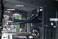
current setup

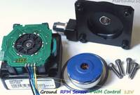
Pump is designed for pc water cooling use and runs idle at 900rpm (my setting).

There are noise dampening kits available but that's not necessary, only if the pump runs at 85 to 100% it's noisy. At idle I hear the fans more and they are on the lowest setting.

Motor type: Electronically commutated, brushless DC, spherical motor
Nominal voltage: 12 V DC
Operating voltage range: 9 to 13.4 VDC
Max. nominal power: (@12 V) 18 W
Max. nominal current: (@12 V) 1.5 A
Max. nominal head: (@12 V) 14.7 ft (4.4m)
Max nominal discharge: (@12 V) ~ 4.75 GPM (17.5 LPM)
Maximum pressure: 22 PSI (1.5 BAR)
Temperature range: Up to 140 °F (60 °C)
Electrical power connector: Molex 4 pin
PWM + RPM Signals: 4-pin connector

20/03/13(Wed)16:39

Heat control and simplicity are the first two goals. RPM control is done with a potentiometer (rheostat). Simple to hook up...line power in to the rheostat and controlled line power out to the motor. Be sure the pump motor can be controlled and that lower rpm's won't burn the motor windings. Also, if the video card cooling system is separate from other cooling, the pump could be located outside the computer where the noise could be dampened easier. You might then need a larger pump because of the water tube length (more stress on the little pump).

20/03/13(Wed)15:01

>>23001 That's already standard. However if I don't hook the pwm connector up it will rev to 4500rpm = 100% and that's loud.

20/03/13(Wed)15:00

I do like the idea, gg. Maybe with a knob so I can control the pump speed myself would be handier. And a LCD so I can see the temp.
I'll bet JC can make one for me (cheap labor ;)

20/03/13(Wed)11:34

Or...forget everything and just have the water pump come on when the p.c. is booted up.

20/03/13(Wed)11:30

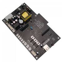
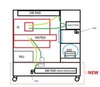
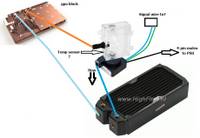
I understand the problem. You already have the parts to do the work. Looking at your diagram in>>22993, you need to add a circut board to tell the parts to go to work. You would capture a temp reading from the sensor, the signal would go through the circuit board (you're building that) and a new signal would be created to tell a relay to open (come on) and turn on the pump. I don't design circuits but the theory is a 'syncro-sevro' type design. The new circuit board might be available in some magazine or electronics store???

20/03/13(Wed)00:46

>>22995 :S there's no temp control..that's the point. There is a temp sensor (in the reservoir) but it just reads the temp, nothing else.

20/03/13(Wed)00:18
52.1
(52.1 Kb, 627x432)

mm..not sure if that will work.. or how (as good I am with building parts, I'm horrible with soldering stuff)

19/03/13(Tue)23:10

Yes, the temperature sensor would be in a reservoir tank as shown.

19/03/13(Tue)23:07

Signal wire from the temp control to the pump motor relay.

19/03/13(Tue)22:15
131.7
(131.7 Kb, 917x636)

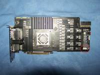
I'm planning on water cooling my graphics card. How can I signal the pump when to rev up when it needs to?
more pix soon